

This post is the third of a five part series on microsoldering. If you haven’t yet, you probably want to check out part 1 and part 2 first.
I’m iFixit’s Lead Teardown Technician, and I decided recently that it was time for me to learn how to microsolder so I can do all the fussy itty-bitty repairs on modern electronics.
Microsoldering is high-value repair: You can fix stuff that manufacturers won’t (like water damage and pry damage), which can save you a boatload of money. So I signed up for Jessa Jones’s Practical Board Repair School. But I can’t keep such important knowledge to myself! If you joined me for Day One and Day Two of microsoldering school, you know I learned that schematics are vital for diagnosing problems and a multimeter is invaluable for locating faulty components.
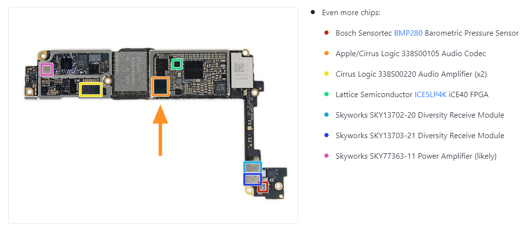
On Day 3 of microsoldering school, we learned how to remove, reball, and replace the very delicate audio IC on the iPhone 7. I’ve recreated the steps involved in reballing and replacing a BGA IC in this post, the examples are not from an iPhone 7.
Audio IC reballing had a moment of fame when many iPhone 7 users experienced what came to be known as “loop disease.” Users would see speaker icons greyed out. They would lose access to Siri. Voice memos didn’t work. The problem, support told customers, was that the audio IC would dislodge from the circuit board—and folks whose phones were out of warranty were out of luck. Reballing the IC was the only solution. Apple eventually agreed to pay out a $35 million settlement to affected users.
And it’s not just audio IC’s from 2016’s iPhones that suffer this type of problem, take the Nintendo Switch’s infamous blue screen of death as one of many examples where reballing IC’s can help correct failings in a product’s design.
Backup a second, what the heck is reballing anyway?
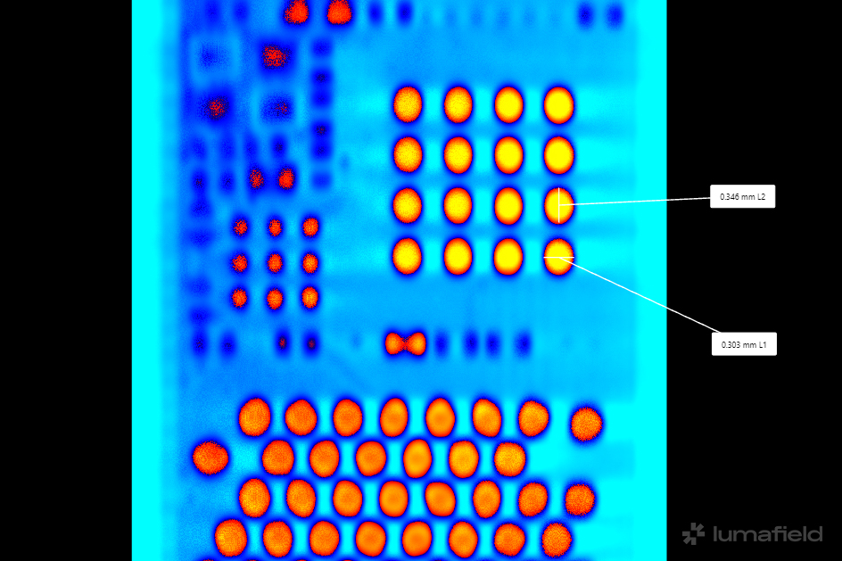
A lot of these tiny ICs are Ball Grid Array (BGA) chips. That means the solder on the pads are, as you might have guessed by now, sphere-shaped and arranged in an array. These solder balls are tiny, with some measuring less than 0.5mm.
You can be sure I’m not shaping these with a pair of tweezers. Instead, we use a tool called a stencil and each stencil is made to accommodate a specific BGA or set of BGAs. We need a malleable solder to fill the openings in the stencil and for that we use solder paste. Solder paste consists of solder powder suspended in flux. It’s a bit like the peanut butter of the soldering world (don’t eat it). But unlike peanut butter, the paste turns into solid solder after you heat it. Each little spot of paste will melt into a ball.
Before we even got to reballing, we had to learn how to remove the audio IC. This thing is insanely fragile, probably because we’re heating an IC that’s barely thicker than the solder balls it sits on. You’ll learn two things from this exercise:
- Maintain very gentle but constant pressure on the edges of the IC.
- Like Gold Five said, “stay on target.” Learning to keep a steady posture prevents slips which cause chips and scrapes that will kill the IC.
Aside from the challenge of removing the fragile audio IC, our main task on day three was preparation: cleaning the old solder from the IC, learning how to apply solder paste through a stencil, and applying heat to the solder in order to create those satisfying spheres.
It looked far more complicated to do than it actually was. The first step is to prepare the IC for reballing:
- Take a clean soldering iron tip (the largest tip that can get the job done as Jessa likes to say).
- Tin the tip, clean it, add flux to the IC and run the tip over all the pads.
- Clean the tip and repeat until all the pads look pretty smooth. You won’t get all the solder off but you should be able to get most of it.
- Examine the IC by tilting it under the microscope to ensure you have an even surface across all the pads.
- Clean the IC with isopropyl alcohol and a cotton swab or similar cleaning tool.
With the IC prepped, we can begin the process of reballing the chip:
- Fetch the appropriate stencil—you can buy these online for your specific need—and position the IC so all the pads are lined up correctly with the stencil.
- Apply a bit of heat resistant kapton tape to keep the IC in place.
- Take a glob of solder paste and using a flat headed blade, spread the paste through the holes in the stencil. Take a sharp angle as you spread the paste and ensure it’s packed into those holes evenly.
- Use a pair of curved or angled tweezers to apply even force on either side of the stencil.
- Continue to apply pressure with your bent tweezers. Switch on your reflow station, set it to something like 360-380C and 60 air zoomies and, as Jessa would say, creep up on the solder paste. Basically, that means approach the stencil slowly with your hot air nozzle. You know you’re close enough when the solder balls begin to form.
It’s important that you apply even pressure on either side of the IC with your tweezers. As we apply heat, the thin metal stencil will want to warp. If the stencil does warp, it’ll create an opening for the solder balls to glob together. We don’t want this, those solder balls must stay separate otherwise we’ll create bridges.
When done right, this is what you’ll see.
Unlike every other soldering project I’ve done, I didn’t need to apply flux when reballing the IC. That’s because the solder paste already has enough flux mixed in. Applying flux separately would just make a mess.
Reapplying the chip to the board involves the same cleaning process as the pads on the IC. Throw some flux on the pads on the PCB and take away as much of the solder as possible. It’s important not to scrape the area with the abrasive copper braid or you’ll end up tearing up the copper pads.
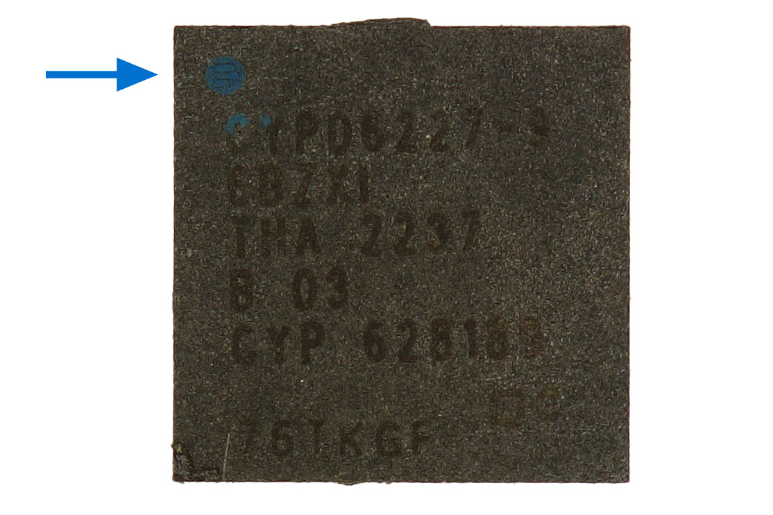
Clean the area with isopropyl alcohol, apply the tiniest amount of flux in the center of the pad and place the IC in position. Make note of where the notch in the chip lines up with the board—that’s pin 1 and needs to line up with pad 1. Some chips will have an arrow or a dot instead of a notch, others are just too small to have a visible notch (in which case, consult the datasheet). You don’t need to worry about aligning the solder balls perfectly to the pads, the solder and flux will take care of that for you.
With the chip in place, creep up with your reflow station, with tweezers at the ready in case they’re needed, using the same settings as before. Be careful not to touch any components in the vicinity of the IC as the pads under all the components in the area will now have liquified solder. After a few seconds, you’ll see an ever so gentle wiggle confirming that the solder balls have adhered to the copper pads.
At this point I breathed a huge sigh of relief and felt a sudden rush as I realized I’d just resoldered an IC. I’d done the thing I’d seen Jessa Jones, Louis Rossman, Justin Ashford, and countless others on YouTube do. But this time, I had done it!
I won’t lie, at this point I felt I could fix anything. And sure enough with a bit more experience, I definitely could!
On Day 4 of soldering school, we’ll be drinking from the firehose as we combine the foundations of what we’ve learned to split a dual layer PCB sandwich on an iPhone logic board…and believe it or not, we’ll be putting it back together in working order. Yikes!


0 Comments