

This post is the second of a five part series on microsoldering. Part one can be found here.
I’m iFixit’s Lead Teardown Technician, and I decided recently that it was time for me to learn how to microsolder so I can do all the fussy itty-bitty repairs on modern electronics. Microsoldering is high-value repair: You can fix stuff that manufacturers won’t, which can save you a boatload of money. So I signed up for Jessa Jones’s mircosoldering school. But I can’t keep such important knowledge to myself! If you joined me for Day One of microsoldering school, you know I learned that schematics are vital for diagnosing problems. But I didn’t actually figure out how to put that into practice—I had to wait for day two.
Day two’s key takeaway was learning how to identify faults on a board and how to identify a short circuit. It’s such a simple process once you have the fundamentals in place—and schematics. After all, what’s the point of being able to remove things from a PCB if you don’t know which thing you need to remove?
A multimeter is your best friend when hunting down electrical faults. If you don’t know how to use one, our guide on multimeter basics can bring you up to speed. The basic functions are exceedingly easy to learn!
Before we start, the types of testing we’re doing here will always be done with the device turned off! Failing to remove the power source from your device may damage the device you’re working on!
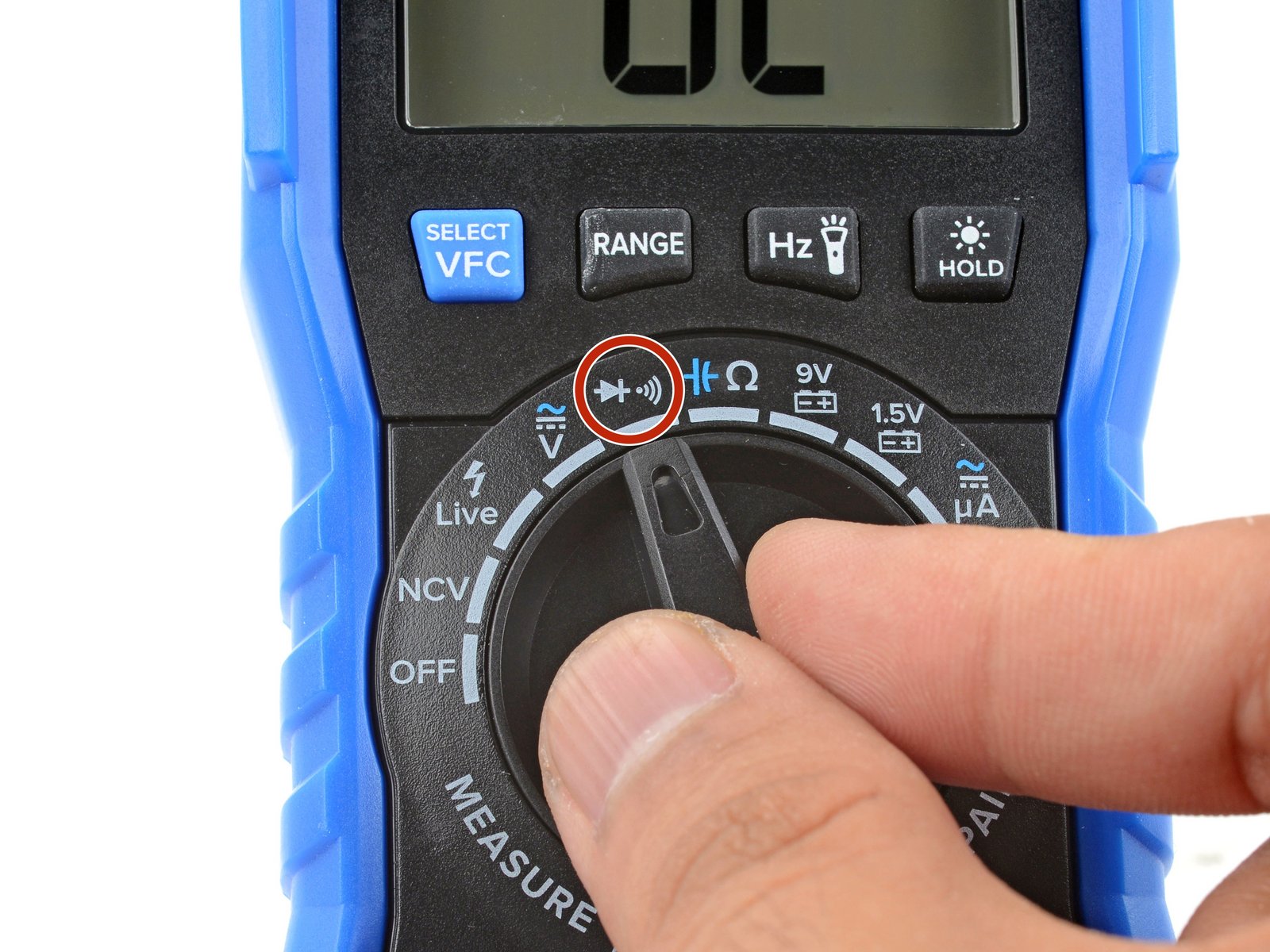
Diode Mode
To figure out whether an electrical component is behaving the way it’s supposed to, you’ve got to put your multimeter in diode mode and measure the readings at the component’s pins.
A small confession: When Jessa taught us about diode mode in microsoldering school, it wasn’t totally new to me. I first encountered it in Justin Ashford’s Repair Journey online course and learned more from him in person and remote over the course of a couple of years. I can’t emphasize enough how powerful this method of troubleshooting can be.
The idea is simple. By placing the multimeter in diode mode, we can inject a specific voltage and current into the ground plane, and we can take a voltage drop reading at the suspected point of failure. This reading should be nearly identical across all working devices of the same type.
A voltage drop reading tells you how much voltage is lost in the circuit due to impedance. People often compare voltage to a garden hose: Voltage is the pressure built up in a hose. Current is the amount of water flowing from a hose. In this case, your hose is the wire. The thickness of the wire dictates the pressure (voltage) that can be safely applied to the wire and the rate of flow (current) through the wire is proportional to the voltage—the voltage drop is the difference in voltage between one end of your wire and the other as the current makes it’s way through various intermediary IC’s and components. To make sense of a voltage drop reading, you need to know how much voltage is typically lost due to impedance in that particular wires journey through all those components . If you see a higher or lower drop, you can bet there’s the electrical equivalent of a kink or a leak in your garden hose.
For example, a diode mode measurement of pin 9 on an iPhone 11 Pro display panel press connector would read around 0.7V drop on every single (working) example of an iPhone 11 Pro. So if we get a reading other than 0.7V drop, we know we have a fault somewhere on that line.
To use this method you’ll need diode mode readings that some good samaritan has posted online. If diode readings aren’t available for your device—and for the vast majority of electronics they won’t be—you’ll need an identical device that’s known to be in good working order so you can take the diode measurements you need and compare it to your own device.
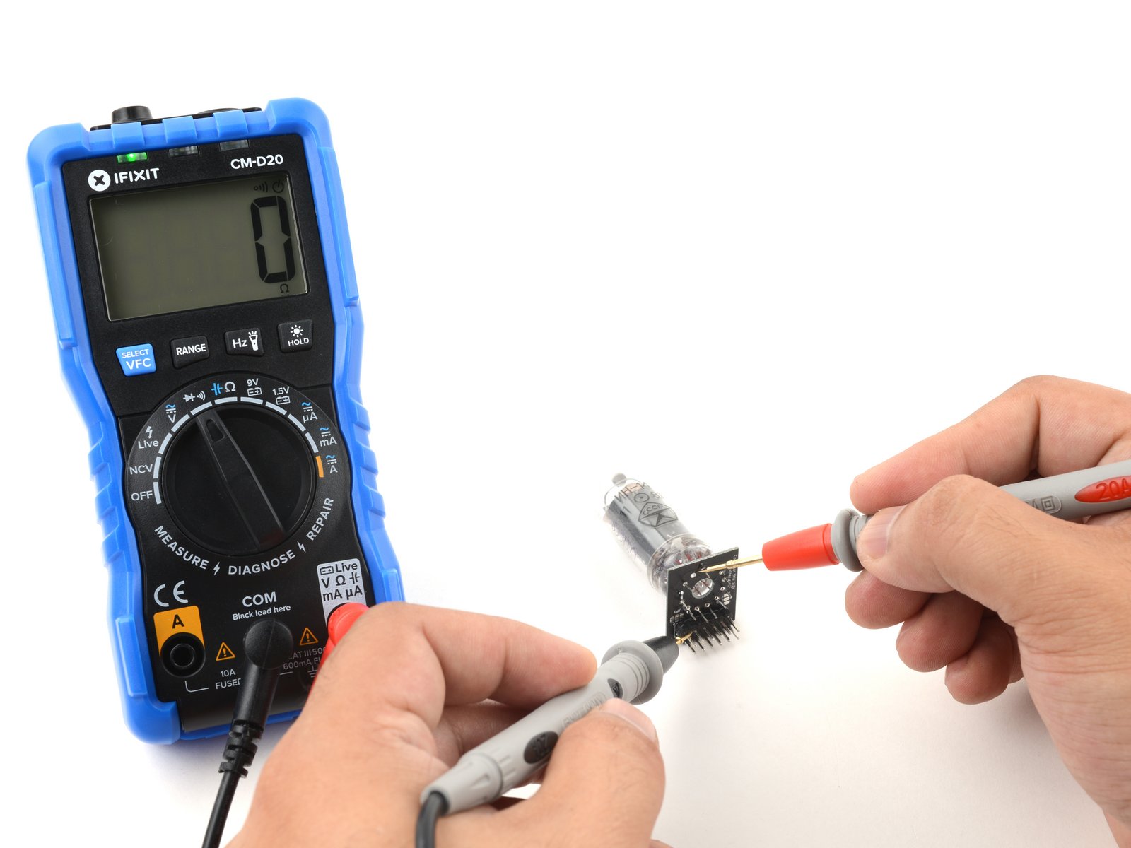
So how does one take diode readings? First place your multimeter in diode mode.
Take the red lead from your multimeter and place the point on a ground pad on your PCB. The black lead from your multimeter will be placed on the pad that you suspect may be shorting to ground. Record and compare the reading you see on the multimeter to the reading from your known good device—or, if you’re lucky enough, the readings listed in the community-produced diagnostic material.
This is a more tedious—and expensive—way of finding information that well documented diagnostic information can provide nearly instantly. For the average consumer, buying a second iPhone to fix the first is not a sensible proposition but in the absence of legislation forcing manufacturers to release the documentation we need to make such repairs, it may just be the best we have.
So if you do find yourself in a position where you can provide diode readings for a device that doesn’t have publicly available schematics, consider posting those readings for others to use.
Short Circuits
Why might a voltage drop be something other than what you expect? Even if you’re totally new to electronics repair, you’ve probably heard about one common problem that results in weird voltage drops: a short circuit.
So what is a short circuit? Commonly referred to as “a short,” short circuits occur when a point on the circuit connects to the ground plane when it’s not supposed to. Ground is generally connected to the negative terminal and carries a voltage of zero.
Sometimes a device will intentionally short to ground but when our circuit is shorted prematurely, the current that is supposed to go from point A to B is being diverted midway to ground and back to the negative terminal. That means B never receives the current it was expecting. Symptoms of a short circuit may include boot loops, a device that only sometimes turns on or doesn’t turn on at all, or even a battery that drains too quickly.

Schematics are extremely valuable when hunting down short circuits. If we take a cellphone as our example, in order to find our short circuit we first need to find the Power Management Unit (PMU) and the power rails that branch out from the PMU integrated circuit (IC). In the iPhone 6, the PMU takes 5V from the Lightning port or around 4V from the battery and converts it to a usable voltage for various components on the PCB. The power rails then distribute each voltage to the appropriate ICs.
When you have schematics, locating the PMU, the power rails, the values assigned to those power rails, and which ICs they lead to is a trivial task.
It’s a little harder to find the PMU without those schematics but with a little experience it’s still a fairly simple enough task. Understanding where the tiny pads underneath the PMU lead to—which capacitors, filters, and ICs—and where those components lead to is an entirely different story. Without that additional information, it can be difficult to tell whether a pin is supposed to lead to ground or if it’s shorted.
One way around this is to place our multimeter in diode mode and test against known good readings. Going back to our earlier example, if we’re testing pin 9 of an iPhone 11 Pro’s display connector and we’re expecting to see a reading of 0.7V but see either 0V or OL, that’s a problem.
OL is displayed when a multimeter’s upper limit for diode mode readings is exceeded and is described as “overload” in most multimeter literature. You’ll often hear it referred to as “over limit” or “open line,” the latter of which is the most self explanatory. It can denote that there’s a break in the line where there shouldn’t be.
Since we’re expecting to see 0.7V, a reading of 0V would indicate a short circuit somewhere on the board. Something, somewhere, is connecting to the ground plane prematurely. Finding that short can range from exceedingly easy to frustratingly difficult. To complicate matters, a short circuit won’t manifest just in the problem area but across that section of the circuit across multiple components. As Jessa likes to say, “a short somewhere is a short everywhere.”
As a newly minted microsolderer, I’ve been leaning on a tool that makes finding that short easier: the thermal camera. By placing a PCB under the thermal camera, we should—in many, but not all cases—be able to see if any spot on the board is getting hotter than it should. This will occur in a shorted out section of the board because the current flowing through the short will be greater than that portion of the circuit is designed to accommodate. This leads to excess heat, which we can observe on the thermal camera.

There are other ways of detecting short circuits, and Jessa encouraged us to use the most powerful tool in our toolbox first: our eyes! Short circuits can be identified in the form of blown capacitors, burn marks, melted and displaced solder, and in the worst cases even smoke.
Wrapping Up
To recap, day two’s learning journey—courtesy of Justin Ashford and Jessa Jones—taught me the foundations of how I might go about isolating a problem on a circuit board. This, in my opinion, is an even more important skill than soldering. By identifying the source of a fault, we also give ourselves the power to correct the fault.
In part three of our five part blog post series on microsoldering, we take a look at the process of reballing an IC and replacing it on the board.


7 Comments
I've reballed and replaced a few BGAs, but I'm looking forward to Part 3 of this series to learn more about the process. I haven't found much info about rebelling by hand (i.e., without an Infrared BGA rework station).
River Saxton - Reply
I think the process looks far more complicated than it actually is. At the end of the day, you're fluxing and soldering copper. The only additional consideration, and this is where practice comes in, is the ability to apply that flux and solder with steady hands. I don't have particularly steady hands but there are definitely ways of dealing with that too. I'll often lower my chair and setup so I can have my elbows on the work surface to provide additional support.
Shahram Mokhtari -
Thank you for this interesting article, and I like your water analogy, likening voltage to pressure and current to flow rate; it is an analogy I often use when I explain electrical circuits to people who do not understand what volts and amps are.
But there is error in your analogy when you say "pressure coming out of the hose than coming into it" Remember that pressure does not "come out of a hose" pressure is "in" the hose; the thing that comes out of the hose is liters per second (or current, e.g., milliamps). Milliamps in equals milliamps out.
I am an engineer and I am very familiar with flow dynamics,and I'm often surprised by people, who should know better, describing the pressure coming out of a hose, or pipe, when what they really mean is the flow rate coming out of the hose and the velocity of the fluid.
I encourage you to get the metaphors correct. It is as important as getting the fundamentals of the theory correct, because if the metaphors are flawed, your readers understanding will also be flawed.
Michael Walsh - Reply
Hi Michael! Thank you for pointing out the error, it should be corrected now.
Shahram Mokhtari -
I Really loved part one and two of this series as a young mobile phone repair guy who dreams of becoming better in repairing iPhones more than most people I know I look forward to part 3. And can I ask what app or website would you recommend for viewing iPhone pcb schematics on an android phone
Emmanuel Eugene - Reply